The equations behind the potentiostat
This article explains the working of a potentiostat more in depth, using Faraday’s law and the Nernst equation. For the basics of the potentiostat, please read the potentiostat article.
A potentiostat controls the potential of the working electrode and measures the current flowing through it. Why not just two electrodes? One of the reasons is that we cannot measure the potential of the working electrode against a fixed point when we just have two electrodes.
Imagine a two-electrode system that consists of the already mentioned working electrode and the electrode, which potential should be our fixed reference point, the reference electrode.
We apply a certain potential between these electrodes and an electrochemical reaction happens at the working electrode, but since the circuit needs to be closed and current needs to flow, a reaction that is inverse to the reaction at the working electrode must occur, that is if oxidation occurs at the working electrode, a reduction must take place at the reference electrode.
Faraday's law
If a current flows at a constant potential, an electrochemical reaction must happen according to Faraday’s law:
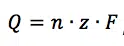
This equation says that the charge Q flowing through an electrode is proportional to the amount n of a species that took or gave z electrons at the electrode. F is the Faraday constant and represents the charge of 1 mol electrons. The current I is the charge Q per time t flowing through the electrode:

The equations 3.1 and 3.2 combination shows that the current I flowing is connected to the reaction happening at the electrode via the amount n:

Nernst equation
Imagine now that the current is flowing at the reference electrode. At this electrode a species’ amount of n is converted. This conversion leads to a change of the surface or the concentration of the solution surrounding the electrode. The Nernst equation shows a clear correlation between the potential E of an electrode and its surrounding:
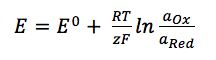
E0 is the standard potential of the redox couple Red and Ox. R is the gas constant and T the temperature. The activity of the oxidized and reduced form of the species aOx and aRed in the surrounding solution is not always easy to predict. This often leads to a simplification of the equation:
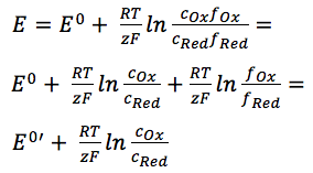
The two activity coefficients fOx and fRed are included in the resulting potential E0’, which is called the formal potential. Since it contains parameters that depend on the environment, such as temperature and activity coefficients, E0’ cannot be listed but needs to be determined for each experiment, if necessary. Most experiments in analytical chemistry are performed at room temperature (295 K). This makes another simplification possible. Out of convenience also the ln will be transferred to the log.
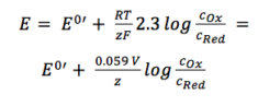
For practical application equation 3.6 is the most used form of the Nernst equation. For many applications one can assume that E0 is roughly the same as E0’, because both of the activity coefficients are close to one.
In this form (equation 3.6) the correlation between the surrounding of an electrode and its potential is visible more easily.
As mentioned before all the simplifications at equation 3.4 were performed: The change of the solution surrounding the reference electrode, due to a flowing current, leads to a change of the potential that is supposed to be our fixed reference point. But we cannot limit the current flow through the reference electrode (RE), because all limitations should be caused by the process that we want to investigate, that is the process at the working electrode (WE).
Using a third electrode
To create a fixed reference point, we use a third electrode.
At this counter electrode (CE), also known as the auxiliary electrode, the counter-reaction to the working electrode’s reactions takes place. The current is flowing between the working and the counter electrode. The potential is controlled between the working and reference electrode (see Figure 3.1).
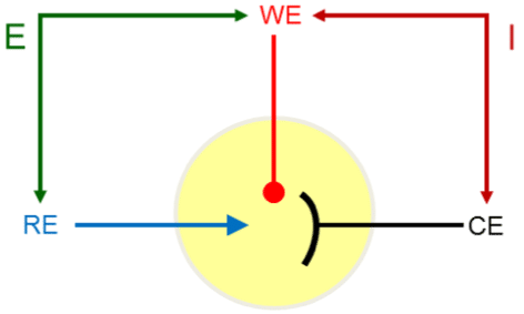
The potential between the counter and reference electrode is adjusted in such a way that the current flowing through the working electrode at a certain potential between working and reference electrode is satisfied. There are limits for the potential a potentiostat can apply between RE and WE (DC potential range) and CE and WE (compliance voltage).
Since you control the potential between RE and WE it is easy to stay within the limits of the DC potential range. The CE has to be bigger than the WE, because the compliance voltage cannot be controlled by the user. A bigger surface at the same potential leads to a higher current and the CE should provide enough current without running into the compliance voltage.
A rule of thumb suggests that the CE should be 100 times bigger than the WE. For many experiments this may not be necessary, but for a good practice you should ensure that the CE is big enough so that it does not limit the current flowing at the WE.
Usually the distance between CE and WE is big enough so the reactions of the two electrodes do not influence each other, and the counter-reaction can be ignored, but sometimes, in small volumes for example, it can be helpful to know which reaction happens at the counter electrode.
The potential is applied between reference and working electrode, while the current flows through working and counter electrode. This way a constant reference point for the potential is maintained.