
Alternate Mode for Multiplexers
In electrochemistry instrumentation, a multiplexer acts as a multi-way valve. The multiplexer switches the potentiostat’s connection between different channels.
Although the nature of the multiplexer limits its operation to sequential measurements, we developed the “Alternate mode” to enable simultaneous-like measurements. During the execution of alternating multiplexer measurements, all chosen channels will rapidly switch within each measurement interval.
Compatible devices
The Alternate mode is compatible with most of our multiplexers.


Alternate measurements
The following techniques support the Alternate multiplexer mode:
- Chronoamperometry;
- Chronopotentiometry;
- Open Circuit Potentiometry;
- (Galvanostatic) Electrochemical Impedance Spectroscopy.
In the Figure below, the potential behavior in each channel for a Chronoamperometry experiment is illustrated.
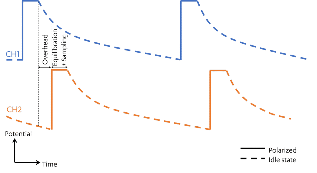
Figure 1 – Applied potential over time for a typical Chronoamperometry with a Multiplexer using the Alternate Mode.
Please note that the active channel is polarized at the set potential only around the moment when its current is being sampled. During the idle period, while other channels are being switched or measured, the Working Electrode of this channel is placed in an idle state.
IMPORTANT REMARK 1/2
It is not possible to apply a potential simultaneously to more than one 3-electrode cell using a multiplexer. This requires a multi-channel potentiostat, where each channel has its own independent potentiostat. Although the Alternate mode can produce a similar response in some cases (for example, with a purely resistive load), the resulting behavior may not be representative or suitable for many electrochemical cells.
Alternate mode with cell arrays
The behavior of the idle channels depends on the selected ‘Unselected WE’ setting. For a detailed explanation of the available options, refer to the PSTrace manual, section “MUX8-R2 settings” for further information. To correctly reach the set potential when choosing “Unselected WE” to GND, all working electrodes must be in the same cell and share a common combined reference and counter electrode (RE+CE). This setting is illustrated in Figure 2 as the arrangement (d).
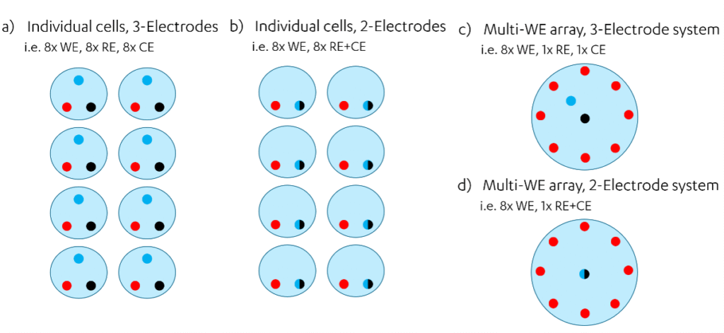
Figure 2 – Examples of multiple electrodes and cells arrangements. The dots represent electrodes in a cell: red = WE, black = CE, blue = RE, black+blue = Combined RE+CE.
If this option is used with a cell array of 3-electrode system (scheme (c)), the behavior is different. The idle channels are polarized at the same cell potential (WE vs. CE) as the active channel. Applying the same cell potential does not necessarily result in the same polarization potential (WE or Sense vs. RE), unless this occurs by coincidence. This is because, in 2-electrode systems, the cell potential and the polarization potential are identical, but in 3-electrode systems they are not.
If this option is used with individual (separate) cells, as shown in schemes (a) and (b), the idle channels are not polarized because their Counter Electrodes (CEs) and Reference Electrodes (REs) are not connected. By forcing a connection between these electrodes—either by physically merging the CE and RE leads—the idle channels become polarized at the same cell potential (WE vs. CE) as the active channel. For 2-electrode systems, where the cell potential equals the polarization potential, this may work for arrangement (b).
IMPORTANT REMARK 2/2
The Alternate mode may not work as expected when using separate (individual) cells. In this configuration, the measured response can differ significantly from the expected behaviour, because the potential applied to each cell does not correspond to the set potential. The only exception is the Open Circuit Potential (OCP) technique, which does not require potentiostat control and therefore provides valid results with separate cells.
Time interval and switching time
For the MUX8-R2 and EmStat4 MUX, the channel switching time is 2 ms. When operating in Alternate mode, the minimum time interval is limited to ensure that the cell has sufficient time to settle after each channel switch:
- When 1 to 8 channels are selected, the minimum allowed interval time is 250 ms
- When 9 to 16 channels are selected, the minimum allowed interval time increases to 500 ms
An important limitation is the time dedicated to sample each measurement point. The actual sampling window is much shorter than that of a sequential measurement. For example, for an interval of 1 second over 8 channels, the actual sampling time on each of the channels is about 0.1 seconds (1/8 and some added overhead). If you require very short time intervals, the measurements may be noisier compared to sequential mode. Most electrochemical cells can handle very short sampling times, but some samples like ion-selective electrodes can be sensitive to this shortening
Charge injection and how to prevent it
Every time a switch is flicked a small charge is injected into the circuit. This is due to the moment when the switch isn’t part of any circuit and thus isn’t controlled by any feedback loop. At the moment the switch is closed the excess charge is injected into the measurement circuit. The charge injection is usually low (20 pC). However, if small electrodes or very sensitive electrodes are used, the charge injection could be sufficient to significantly change the potential of the electrode. In consecutive mode, there is only one switching event and afterwards the electrode has the whole measurement duration to re-establish its OCP. If the Alternate mode is used, however, there are many switching events and very small time intervals for the measurement. As a result, the electrode gets a lot of charge injections and little time to stabilize its OCP. This leads to artifact OCP measurements in some cases. In order to mitigate this issue:
- If you have a EmStat4 MUX, simply leave the Counter Electrode and Working Electrode leads disconnected. Sense and Reference Electrode leads are buffered against this effect and are sufficient for OCP-only experiments.
- If you have a MUX8-R2, read this application note to see how to avoid the charge injection.