
How to connect a potentiostat to a battery
To connect a potentiostat to a battery, connect the working electrode lead to the positive terminal and the counter and reference electrode leads together to the negative terminal. This two-electrode setup measures the full cell voltage. For low-impedance measurements such as EIS, give each terminal a separate current lead and sense lead (four-terminal or Kelvin connection).
Always switch the potentiostat on before you connect the battery, and check that the battery voltage fits within the instrument’s potential range.
A battery is an active sample: it can push current into your potentiostat. Connect it last, disconnect it first.
Still deciding whether a potentiostat suits your battery research? Read Why would you use a battery analyzer? first. This article starts where that one ends: with the instrument on your bench and a battery ready to connect.
Before you connect: three checks
Voltage. The open circuit voltage of the battery must fall within the potential range of your potentiostat. A single Li-ion cell (around 3 to 4.2 V) fits within a ±5 V range. A 12 V lead-acid battery does not fit within ±10 V.
Current. Check the maximum current you plan to apply or draw. A coin cell experiment at a few milliamps works on most potentiostats. Charging or discharging larger cells at hundreds of milliamps requires an instrument such as the Nexus, which supports up to 1 A.
Power. The potentiostat must be on and connected before the battery is attached. A charged battery connected to an unpowered potentiostat can damage the instrument, as there is no protection against current flowing back into it.
Step by step: the two-electrode connection
This is the standard way to measure a full battery cell. On a PalmSens cell cable, the working electrode lead is red, the counter electrode is black, the reference electrode is blue and the sense lead is white or yellow.
- Switch on the potentiostat and connect it to PSTrace.
- Stack the reference electrode plug (blue) on top of the counter electrode plug (black).
- If your instrument has a sense lead, stack the working electrode plug (red) onto it.
- Connect the counter and reference leads to the negative terminal of the battery.
- Connect the working electrode (and sense) lead to the positive terminal.
- Run an open circuit potential (OCP) measurement first. A positive value equal to the expected cell voltage confirms the polarity is correct.
Only start a technique that applies potential or current after the OCP check.
In this setup the potential is applied and the current flows between the same two terminals. The result includes both electrodes, the electrolyte and the separator. That is exactly what you want when the full cell voltage is the parameter of interest.
Four-terminal connection for EIS and high currents
Every cable has resistance. A typical PalmSens cell cable has about 0.2 Ω, so a current of 100 mA causes a 20 mV drop across the cable. With the leads stacked at one clip, that drop and the contact resistance end up in your measurement.
For most measurements this is negligible. For a battery it is not, because the internal resistance of a Li-ion cell is often in the milliohm range. In a two-terminal EIS measurement the cable and clip resistance can then be larger than the battery’s own resistance.
The solution is to separate the leads that carry current from the leads that measure potential. Connect the working electrode lead and the sense lead to the positive terminal with separate clips. Connect the counter electrode lead and the reference electrode lead to the negative terminal with separate clips.
Now the sense and reference leads measure the potential directly at the battery terminals, where almost no current flows through them. This is called four-terminal or Kelvin sensing. PalmSens instruments with a sense lead, such as the Nexus and the EmStat4 HR, support this setup.
In EIS on batteries, the way you connect the leads changes the result more than the instrument settings.
One more tip for potentiostatic EIS: set the DC potential relative to the OCP, not to 0 V. Otherwise the potentiostat will try to pull the battery to 0 V and drive a large current. Galvanostatic EIS (GEIS) with a small current amplitude is a common alternative for low-impedance cells.
Instruments for battery measurements
Both instruments have a sense lead for four-terminal measurements. The difference is how much current your battery tests need.
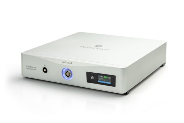
Nexus
For charge-discharge and EIS on larger cells
- Up to ±1.1 A and ±10 V
- Sense lead for four-terminal EIS
- Second sense lead (S2) for Dual EIS
- 32 GB internal storage for long cycling tests

EmStat4S HR
For coin cells and small pouch cells
- Up to ±200 mA and ±6 V
- Sense lead for four-terminal EIS
- EIS up to 200 kHz
- USB-powered and palm-sized
Measuring the anode and cathode separately
A commercial battery has two terminals, so you can only measure the full cell. In a lab test cell with a third, reference electrode you can also look at each electrode on its own.
In that case connect the working electrode to the cathode, the counter electrode to the anode and the reference electrode to the reference. The Nexus has a second sense lead (S2) that measures an extra potential at the same time. With Dual EIS, it records the impedance of anode and cathode in a single measurement.
What to measure after connecting
Start every session with an open circuit potential measurement. It confirms the polarity and shows the cell voltage without drawing current, which is also the value you need when you set up EIS relative to the OCP. Which tests follow, from charge-discharge curves to impedance, depends on your research question. An overview of battery measurements and their names is on Why would you use a battery analyzer?
Safety when working with batteries
Connect the battery last and disconnect it first. Disconnect it before you switch off the potentiostat or update its firmware.
Keep crocodile clips apart: if they touch while connected to the battery, they short-circuit it. A short-circuited Li-ion cell can heat up quickly.
Stay within the battery manufacturer’s limits for voltage and current, also during charging. A potentiostat follows the method you set, not the safe limits of the cell.
For coin cells, a dedicated holder such as the ItalSens Coin Cell Battery Holder gives a stable contact and connects directly to the 2 mm banana plugs of a PalmSens cable.
Connection specifications of PalmSens potentiostats
These three values decide how you can connect a battery: the potential range, the maximum current and whether the instrument has a sense lead for four-terminal measurements.
| Instrument | Potential range | Max. current | Sense lead |
|---|---|---|---|
| Nexus | ±10 V | ±1.1 A | Yes, plus second sense lead (S2) |
| EmStat4S HR | ±6 V | ±200 mA | Yes |
| PalmSens4 | ±5 V or ±10 V | 10 mA range | No |
Frequently asked questions
Which lead goes to the positive terminal of the battery?
The working electrode lead, together with the sense lead if your instrument has one. The counter and reference leads go to the negative terminal. With this connection a charged battery shows a positive voltage.
Do I need a reference electrode to test a battery?
Not for a full-cell measurement. In a two-electrode setup the reference lead is connected to the negative terminal together with the counter electrode. A separate reference electrode is only needed to measure the anode or cathode on its own.
Why does my EIS measurement show a higher resistance than the battery datasheet?
In a two-terminal connection the resistance of the cable, the clips and the contacts is added to the battery resistance. A four-terminal connection removes most of that. Contact resistance at the terminals and the state of charge also affect the result.
Can I connect a 12 V battery to a potentiostat?
Only if the potential range of the instrument covers the battery voltage. Many potentiostats are limited to ±5 V or ±10 V, which is too low for a 12 V battery. Single cells are within range of most instruments.