How to fit easily
Sometimes fitting software just doesn’t seem to work properly and the fit values aren’t even close to the measured values. This can be due to bad starting values for the fit. In this section some guidelines to find good starting values for fitting are given.
Finding the right fit
Often a fit will be pretty good with the first iteration. Sometimes, a fit just won’t deliver a curve which overlaps with the measurement. This is due to the way a fit is calculated. The computer tries to find values for the variables that deliver a curve with the smallest difference to the measurement (Least Square fitting).
A drawback of the Complex Non-linear Least Squares fitting algorithm is that when given initial values for parameters that are too far off the absolute minimum it can get stuck in a local minimum and return a suboptimal fit.
Unfortunately, the default initial values for the resistors and capacitors are sometimes too far off from the optimal values for some systems. The default values have been selected to be optimal for the most common types of electrochemical cells.
In order to obtain a correct fit when modelling coatings/corrosion with equivalent circuits the following steps are recommended, if a clear RC system is visible (semi-circle in Nyquist plot).
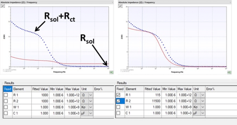
In the fitting window switch the view to the absolute impedance over frequency.
The solution resistance Rsol can be read from the right side of the plot (high frequency). Enter this value into the fitting parameters. The plot is directly updated after editing a value. You can, of course, also read this value from the Nyquist plot (start of the semi-circle).
For estimating of the charge transfer resistance Rct use the value of the impedance at the left side of the plot (low frequencies), where the slope of the curve is suddenly decreasing. Enter this value into the fitting parameters. The plot is directly updated after editing a value. You can, of course, also read this value from the Nyquist plot (end of the semi-circle).
The capacitance of the constant phase element or the capacitor can then be lowered, for instance 0.001 µT/µF is a good value. If your change of capacitor’s value was good, it will become clear when the plot is updated.
Next press fit to obtain the fit with the correctly fitted values of the resistors and the constant phase element.
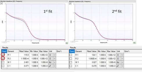
Sometimes it is necessary to fix the known values before the first fit, than release them and fit again. The first fit will bring the not known values close to the optimum and the second one will optimize all parameters.
Although these steps have been quite specific for RC systems, they can be used analog for other circuits. First, values are estimated from the measurement and afterwards a fit with these parameters fixed is performed to determine the values of the other parameters. Afterwards a fit with no fixed parameters is performed.