Capacitive Current
Understanding capacitive charging current is important for understanding electrochemical experiments, so in this section the origin and equations for capacitive charging current will be explained. Afterwards the effect of capacitive current during Cyclic Voltammetry and Linear Sweep Voltammetry is discussed.
Definition of the Capacitive Current
Usually, electrochemists are interested in the Faraday current which is the current caused by an electrochemical reaction. The capacitive current, caused by physics, is an unwanted side effect. The cause of this current is ions accumulating in front of the electrode.
These ions and the electrode’s charged surface form a capacitor. A capacitor will store a charge Q depending on the potential E across the capacitor and its capacitance C:

What does this mean for measurements? If the potential of the electrode is changed, for example during a potential step, the amount of charge the capacitor stores changes, and a current will flow that has no chemical but only a physical meaning. This is the current that charges or discharges the capacitor also known as capacitive charging current or short capacitive current. This current decays exponentially with time t as known from electronics (see Equation 4.2).
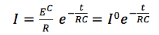
EC is the charging potential or voltage, I0 is the starting current, R is the resistance of the circuit around the capacitor, and C the capacitance of the capacitor. This decay is much faster than the decay of Faraday current if sufficient reactant is present.
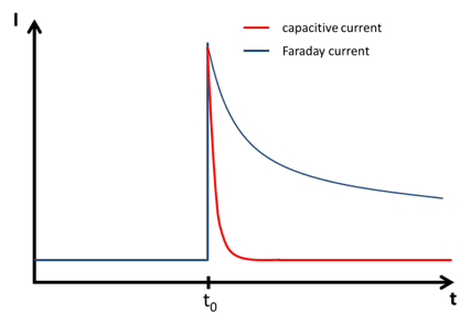
It is well known that for reactions involving a free diffusing species in solution the Faraday current decays with t-½. This means that the capacitive current decays much faster than the Faraday current. The difference between the decay of capacitive current and the Faraday current of a free diffusing species is shown as a scheme in Figure 4.5.
Capacitive current during sweep voltammetry and cyclic voltammetry
During linear sweep voltammetry or cyclic voltammetry, the potential of the electrode is changed continuously and linear during the whole measurement. This means during a linear sweep a constant capacitive current is flowing. This can be deducted from the definition of current I, which is charge Q per time t, and Equation 4.1:
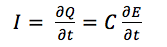
Equation 4.3 shows the higher the capacity C is the higher is the capacitive current. The capacity C for a plate capacitor can be calculated with
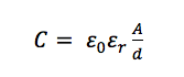
where ε0 is the electric field constant, εr is the relative permittivity of the medium between the plates, d is the distance between the two plates and A is the surface area of the two plates.
Most factors influencing the capacity cannot be altered in an electrochemical experiment. The constant ε0 cannot be changed. The distance d and the relative permittivity εr can only be changed by changing the solution, because d is defined by the distance between the electrode’s surface and the layer of ions. εr is a property of the solvent. The area of the electrode A is influenced by the surface roughness. The rougher a surface is the higher is its surface area. This means A is a parameter we can actually influence. If the working electrode is a reusable electrode, a proper polishing that leads to a smooth surface can reduce A and thus capacitive current drastically.
Fortunately, digital potentiostats don’t provide a true linear sweep. Analog potential provides a true line for a potential sweep. A digital potentiostat can only apply discrete values. This property makes it necessary to approach the linear increase by performing small potential steps. These small steps are approximately a line. Just like a circle is formed out of pixels on a screen, if you zoom in enough, you will see the steps and edges. During one of these steps capacitive current behaves according to Equation 4.2 and not Equation 4.3, because it is not a continuous change, but small increments of steady potentials. Only the last quarter of a potential step increment is used for the measurement and most of the capacitive current is already decayed there according to Equation 4.2.
As a result measurements with digital potentiostats that don’t offer a true linear option will always show a significantly smaller capacitive current than the theory for a true linear sweep predicts. The advantage is the major part of the capacitive current is suppressed. The disadvantage is that digital potentiostat can’t perform measurements where the exact capacitive current needs to be measured.
See PalmSens4 digital potentiostat