


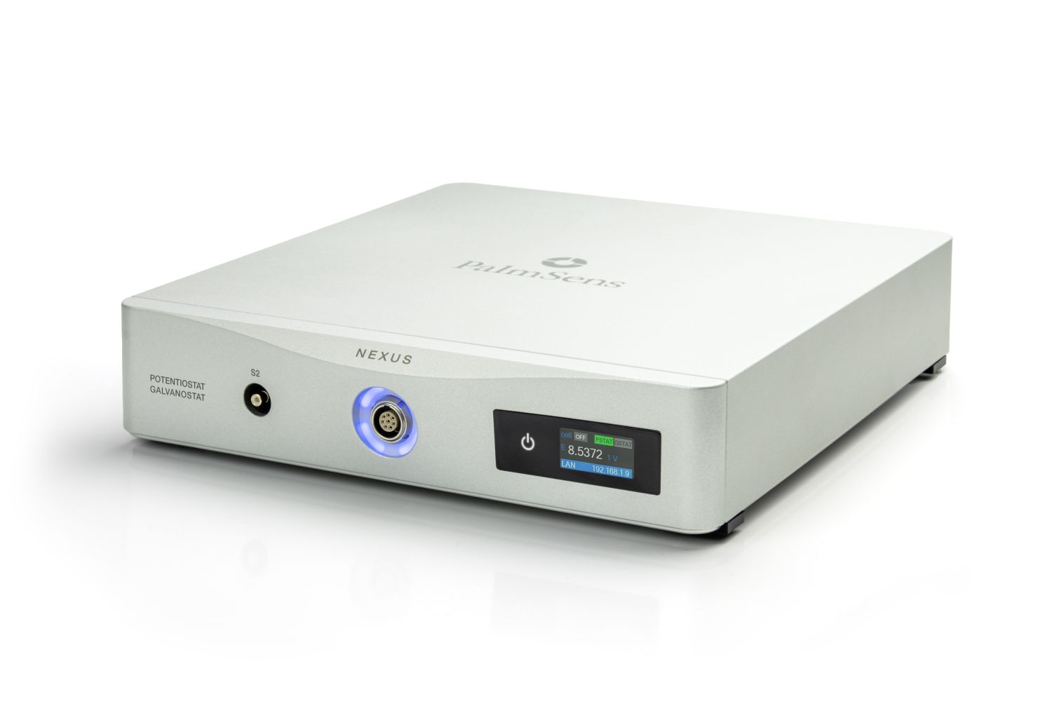


Nexus
Engineered for Electrochemical Excellence
- (Bi)Potentiostat/ Galvanostat/ Impedance analyzer
- FRA / EIS: 10 µHz up to 1 MHz
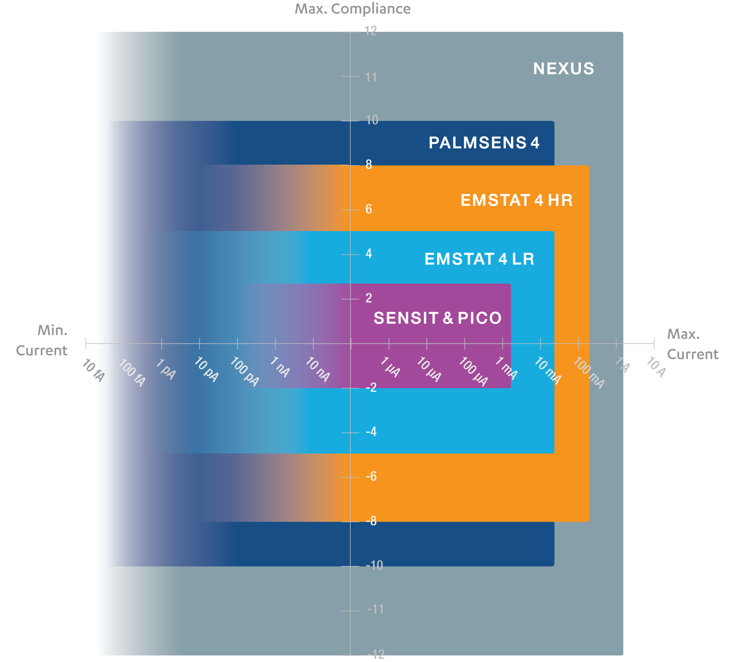
- 11 current ranges: 100 pA to 1 A
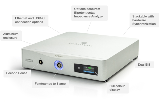
- Dual EIS with second sense electrode
- Script your experiments using MethodSCRIPT
- Use with PSTrace software for Windows
Description
Building on PalmSens’ legacy of providing top-tier solutions for accurate low-current measurements, Nexus delivers an ultra-low-noise performance that exceeds even our existing portable devices, while also supporting measurements up to 1 Ampere.
Versatile
Our high-end instrument, the Nexus, is a Potentiostat, Galvanostat, and optional a Frequency Response Analyser (FRA) for Electrochemical Impedance Spectroscopy (EIS). The Nexus has a large potential range (-12 V to +12 V) and current range (100 pA to 1 A) with a high resolution and low noise.
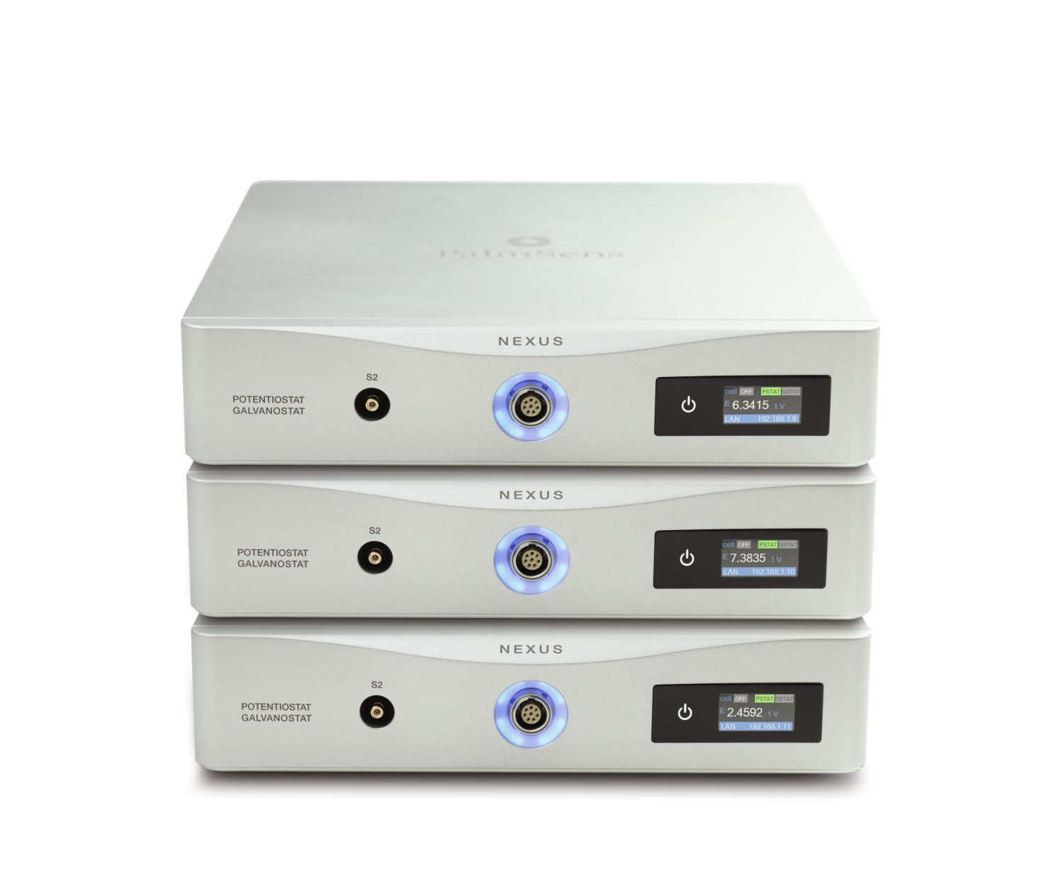
The research software PSTrace makes using the Nexus a breeze. The scripting language MethodSCRIPT gives a user full control when needed. Looking for a multi-channel instrument? Just stack multiple instruments on top of each other.
Configurable
Nexus comes in different configurations:
- optional EIS/FRA module with maximum frequency of 1 MHz
- optional BiPotentiostat module for second WE
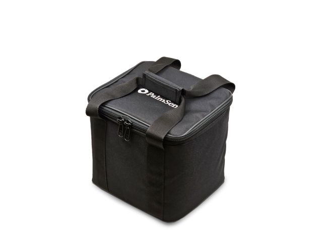
Standard included
Carrying padded bag containing:
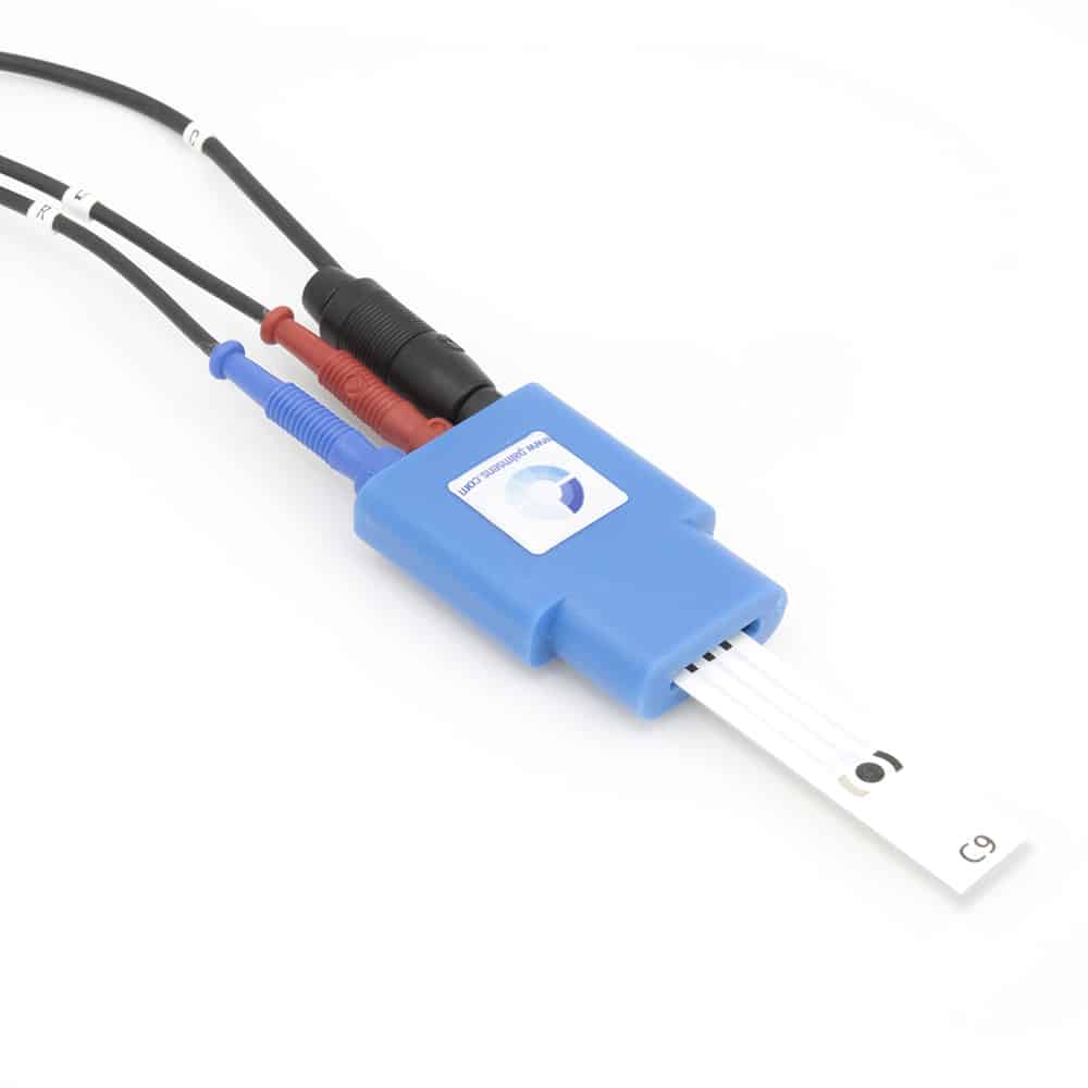
- High quality, double shielded cell cable with
2 mm banana connectors for Working, Sense, Counter, Reference electrode and Ground - Chassis ground cable with croc clip (4 mm)
- Hardware Sync Link cable
- Crocodile clips
- Calibration report
- Dummy cell
- USB cable and Ethernet cable
- Manual and Quick Start document
- PSTrace software for Windows
- iR-compensation (ohmic drop compensation) module
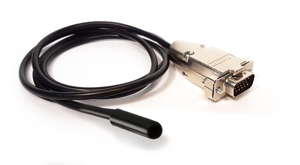
- Second Sense lead cable
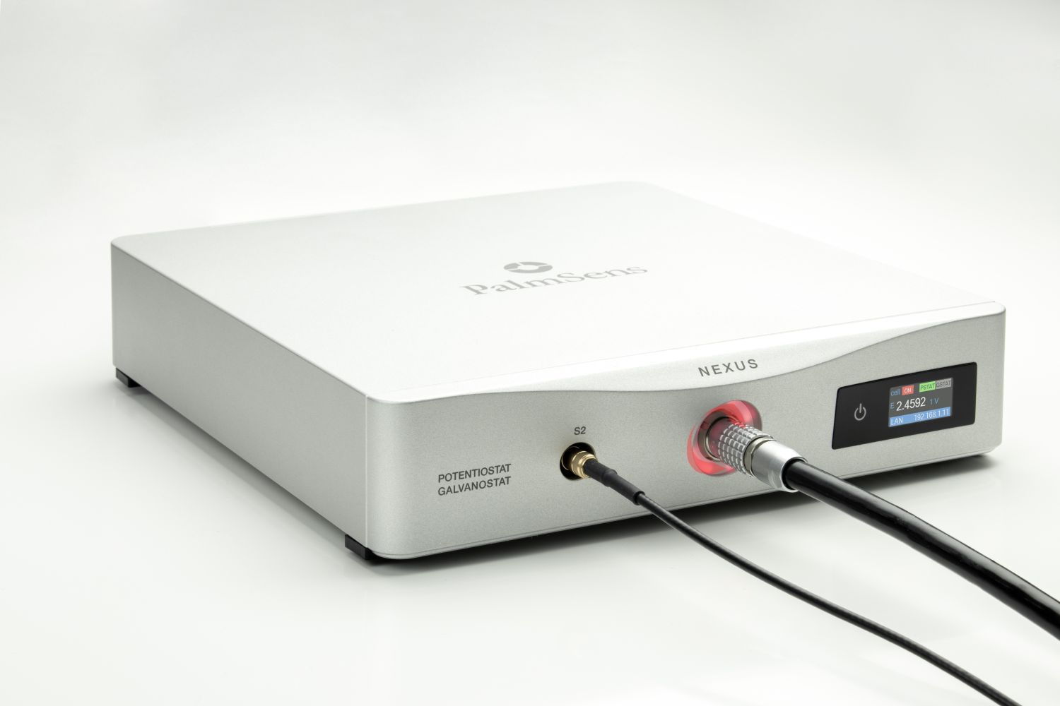
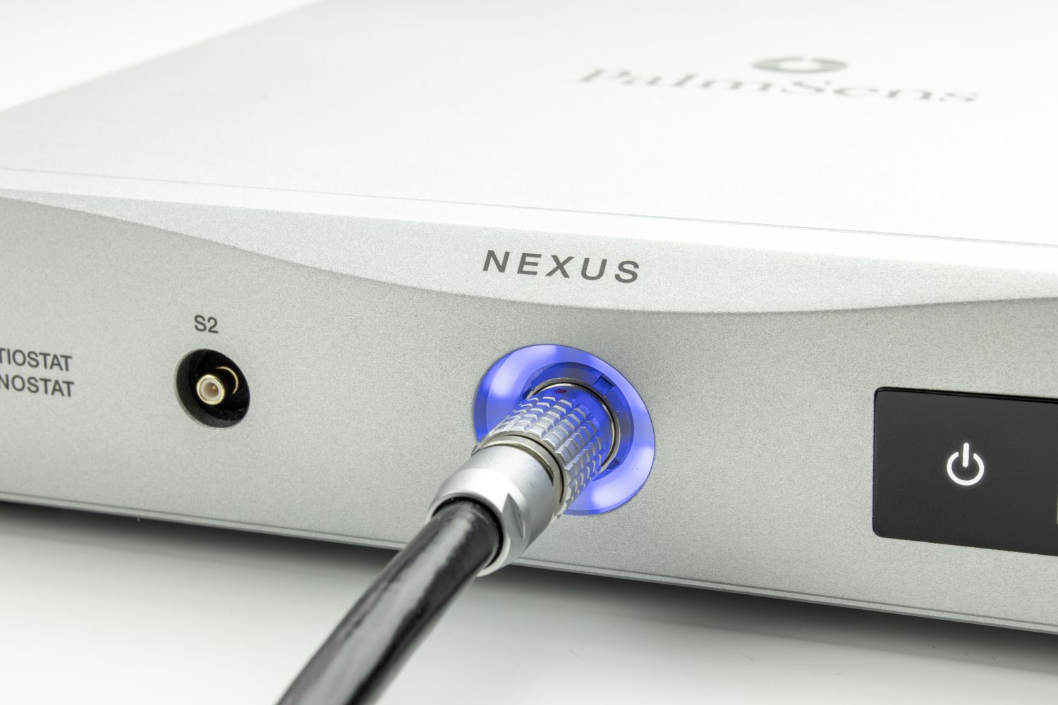
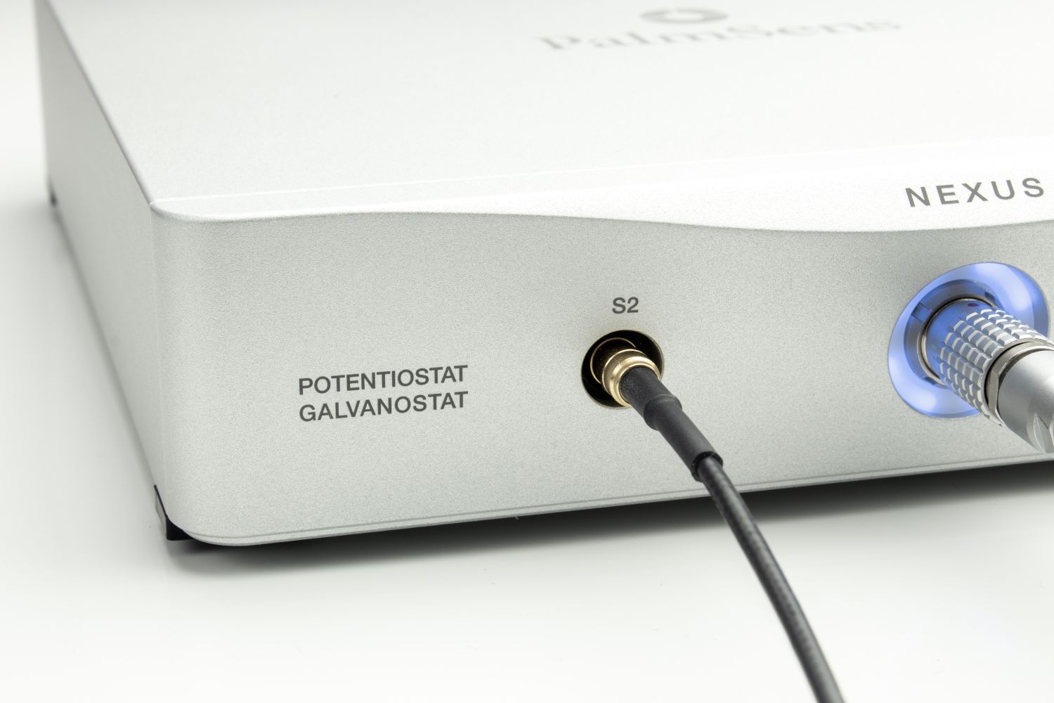
S2 and BiPot
Nexus includes a Second Sense lead (S2) and an optional BiPotentiostat (BiPot) module.
S2 – Additional voltage (potential) measurement point
BiPot – Independent second working electrode for simultaneous current measurement
These two features are independent and serve distinct purposes:
- S2 (Second Sense Lead)
S2 acts as an additional voltage-sensing input, with the same specifications as the main reference electrode. It measures the potential at a specific point in the cell and, because the current at that point is known, it can also be used to calculate impedance. - BiPot (BiPotentiostat Module)
The BiPot module introduces a second working electrode (WE2), operating versus the same reference and counter electrodes as the main channel. In BiPotentiostat mode, both working electrodes (WE1 and WE2) are recorded simultaneously. WE2 operates in potentiostatic mode, meaning it can independently control its potential and measure its current. Refer to our BiPotentiostat article to check which techniques are available when using this mode.
Why choose the Nexus?
Typical research fields

Always a backup
Every Nexus is equipped with an internal storage of 32 GB. This means all your measurements can automatically be saved on-board as backup.Measurements can be browsed and transferred to the PC easily using the PSTrace software for Windows.
Accessories
Accessories for the Nexus
You may also like…
Specifications
| General | |
|---|---|
| potential range | ±10 V |
compliance voltage
The compliance voltage is the maximum voltage that can be applied between the working and counter electrode. Another name could be the maximum cell potential. Continue reading
| ±12 V |
| maximum current | ±1.1 A |
| impedance analyzer¹ (FRA/EIS)
FRA stands for Frequency Response Analyzer. It is an analyzer used to measure impedance (EIS-Electrochemical Impedance Spectroscopy). In PalmSens instruments it is a module integrated in a potentiostat, optional for most models Continue reading
| 10 µHz to 1 MHz |
| sample connections | WE, WE2¹, S, S2², RE, CE and GND |
|
|
| Potentiostat | |
|---|---|
applied dc-potential resolution
The lowest observable difference between two values that a measurement device can differentiate between.
| 78 µV |
applied potential accuracy
The applied potential accuracy describes how close to the real values your applied potential is.
| ≤0.1% ±1 mV offset |
current ranges
A current range defines the maximum current a potentiostat can measure in a certain range. Continue reading
| 100 pA to 1 A (11 ranges) |
| maximum measured current in each current range | ±1.1 times CR for 1 A range ±4.5 times CR for 10 mA range ±5 times CR for all other ranges |
| measured current accuracy
The current accuracy describes how close to the real values your measured current is. Continue reading
| < 0.1% of value ±10 pA (bias) ±0.1% of range (offset) |
measured current resolution
The lowest observable difference between two values that a measurement device can differentiate between. Continue reading
| 0.0038% of CR
CR is the acronym we use for Current Range. A current range defines the maximum current a potentiostat can measure in a certain range. Continue reading
(3.8 fA on 100 pA range) |
| Galvanostat | |
|---|---|
current ranges
A current range defines the maximum current a potentiostat can measure in a certain range. Continue reading
| 1 nA to 1 A (10 ranges) |
| applied dc-current | ±1.1 times CR for 1 A range ±4.5 times CR for 10 mA range ±5 times CR for all other ranges |
| applied dc-current resolution | 0.0038% of applied current range |
| applied dc- current accuracy
The current accuracy describes how close to the real values your measured current is. Continue reading
| < 0.1% of current ±10 pA (bias) ±0.1% of range (offset) |
| potential ranges | 10 mV, 100 mV, 1 V |
| measured dc-potential resolution | 78 µV at ±10 V (1 V range) 7.8 µV at ±1 V (100 mV range) 0.78 µV at ±0.1 V (10 mV range) 78 nV at ±0.01 V (1 mV range) |
| measured dc-potential accuracy | < 0.05% of value ±1 mV (offset) |
More details in the product brochure.
| Impedance Analyzer | |
|---|---|
| Potentiostatic mode (PEIS)
During a conventional EIS (PEIS) a potential sine wave is applied and the resulting current is measured. Continue reading
|
|
| frequency range | 10 µHz to 1 MHz |
| ac-amplitude range | 1 mV to 0.3 V RMS (full range) 1 mV to 1.4 V RMS for frequencies up to 1 kHz |
| Galvanostatic mode (GEIS)
During GEIS a current sine wave is applied and the resulting potential is measured. Continue reading
|
|
| frequency range | 10 µHz to 1 MHz |
| ac-amplitude range | 0.001 * range to 0.15 * range RMS (full range) 0.001 * range to 0.74 * range RMS for frequencies up to 1 kHz |
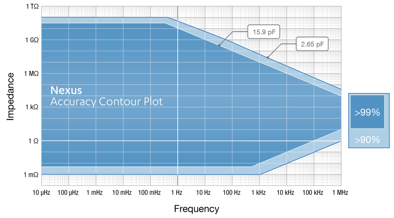
| EIS Accuracy Contour plot | |
|
|
| Electrometer | |
|---|---|
electrometer amplifier input
The amplifier input resistance of the amplifier in the electrometer determines the load that the amplifier places on the source of the signal being fed into it. Ideally the resistance is infinite, and the load to be zero to not to influence your measurement.
| > 10 TΩ // 10 pF |
bandwidth
Bandwidth defines the range of frequencies a system can accurately measure or respond to. Continue reading
| 500 kHz |
| Data acquisition | |
|---|---|
| max. offline rate (to buffer) | 1M points/s (max. 50k points) |
| max. online rate | 2500 points/s |
| ADC/DAC | 18-bit
An 18 bit input can measure in 2^18 or roughly 262 thousand different steps. If you measure for example an analog voltage that can go from 0 to 5V, the accuracy is 5 divided by 262k, resulting in resolution of 20 uV. Continue reading
|
| internal storage space | 32 GB (sufficient for more than 800 million data points) |
| BiPotentiostat | |
|---|---|
dc-potential range
The maximum potential difference, that can be applied between WE and RE.
| ±5 V |
| applied potential resolution | 153 µV (16-bit) |
applied potential accuracy
The applied potential accuracy describes how close to the real values your applied potential is.
| ≤ 0.1%, ± 1 mV offset |
current ranges
A current range defines the maximum current a potentiostat can measure in a certain range. Continue reading
| 100 pA to 10 mA (9 ranges) auto-ranging available |
| maximum measured current | ±45 mA |
measured current resolution
The lowest observable difference between two values that a measurement device can differentiate between. Continue reading
| 0.0038% of CR
CR is the acronym we use for Current Range. A current range defines the maximum current a potentiostat can measure in a certain range. Continue reading
|
| measured current accuracy
The current accuracy describes how close to the real values your measured current is. Continue reading
| ≤ 0.1% of current 0.1% of range (offset) |
| IR-compensation | |
|---|---|
| purpose | ohmic drop compensation
iR compensation or ohmic drop compensation is a compensation of the residual resistance between RE and WE (or S). While it is usually negligible, it can be significant for high currents and poor-conductive electrolytes. Continue reading
|
| compensation method | positive feedback |
| resolution of MDAC used for correcting potential | 16-bit |
| max. compensated resistance | 1 MΩ |
| max. bandwidth
Bandwidth defines the range of frequencies a system can accurately measure or respond to. Continue reading
(when iR-compensation is enabled) | 10 kHz |
| auto-ranging | not possible when IR-compensation is enabled (manual only) |
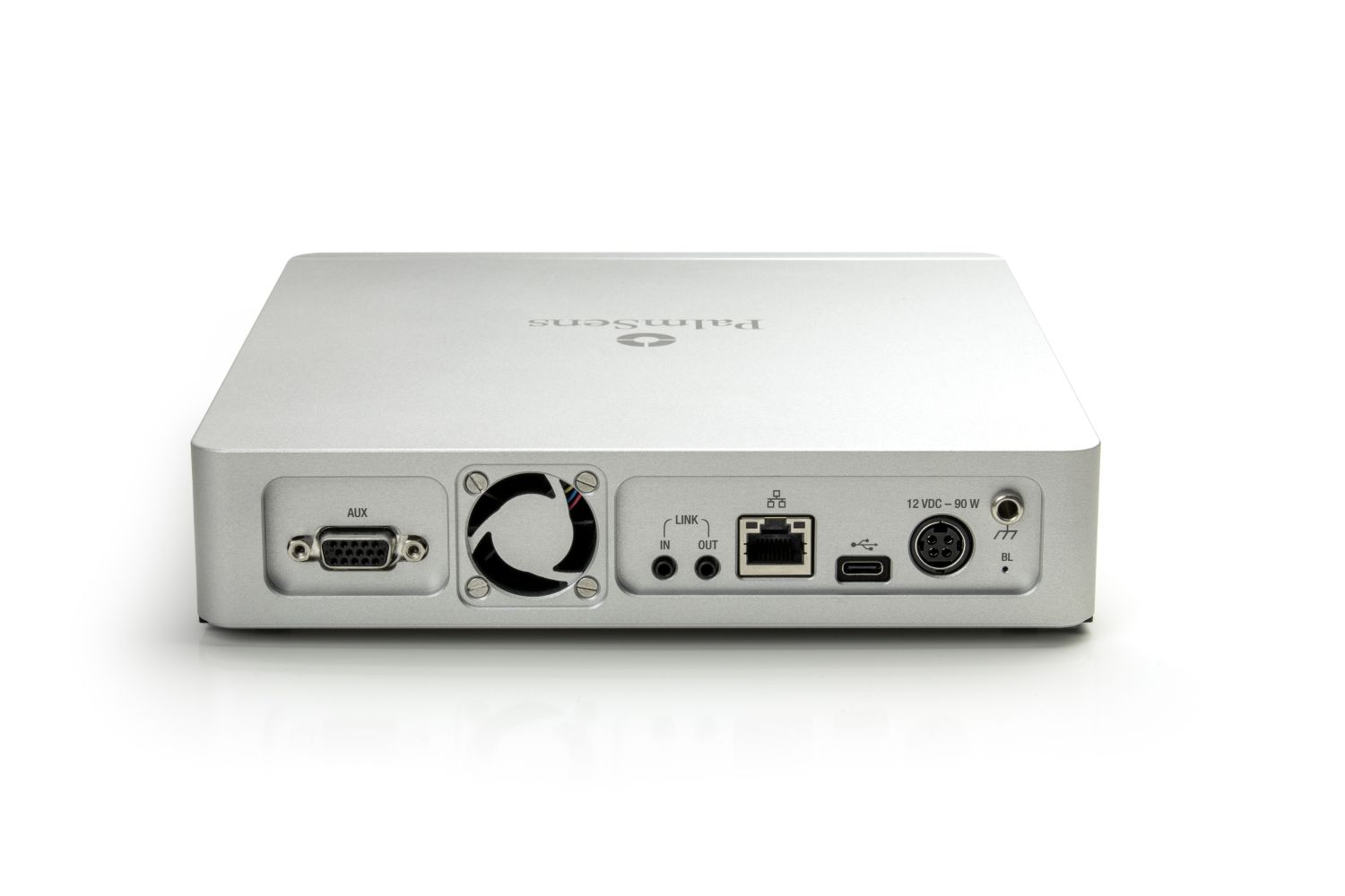
| Auxiliary port | |
|---|---|
| connector | D-Sub 15 |
| analog input | ±10 V, 18-bit
An 18 bit input can measure in 2^18 or roughly 262 thousand different steps. If you measure for example an analog voltage that can go from 0 to 5V, the accuracy is 5 divided by 262k, resulting in resolution of 20 uV. Continue reading
|
| analog output | 0-10 V, 16 bit (1 kΩ output impedance) |
| digital I/O | 6x digital input/output (3.3 V) |
| E-monitor | E-out ±13 V (2.5 kOhm output impedance) |
| i-monitor | i-out ±10 V at 1 nA – 100 mA current range ± 2 V at 1 A current (2.5 kOhm output impedance) |
| power line | 5 V output (max. 300 mA) |
| Other | |
|---|---|
| electrode connection | 2 mm banana pins for RE, WE, WE2, CE, GND, Sense and Sense 2 |
| housing | aluminium body: 20 x 21 x 4.5 cm³ |
| weight | 1.8 kg |
| power | external AC-DC adapter (100-240 VAC, 50-60 Hz to 12 VDC), included |
| communication | ethernet and USB-C |
Software
PSTrace
PSTrace is designed to be productive immediately after installation, without going through a long learning period. It has three modes; the Scientific mode which allows you to run all the techniques our instruments have to offer, and two dedicated modes for Corrosion analysis and the Analytical Mode. PSTrace is suitable for all levels of user experience.
Features include:
- Direct validation of method parameters
- Automated peak search
- Equivalent Circuit Fitting
- Scripting for running an automated sequence of measurements
- Open data in Origin and Excel with one click of a button
- Load data from the instrument’s internal storage
- and many more…
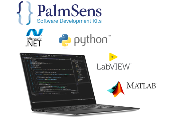
Software Development Kits
PalmSens provides several Software Development Kits (SDKs) to help developers create custom software to control their potentiostat. Each SDK comes with documentation and examples that shows how to use the libraries.
SDKs are available for:
- .NET (WinForms, WPF and Xamarin for Android)
- Python
- LabVIEW
- Matlab
MethodSCRIPT™ Communications Protocol
The Nexus works with MethodSCRIPT™, giving you full control over your potentiostat. The simple script language is parsed on-board, which means no DLLs or other type of code libraries are required. MethodSCRIPT™ allows for running all supported electrochemical techniques, making it easy to combine different measurements and other tasks.
MethodSCRIPT can be generated, edited, and executed in PSTrace.
MethodSCRIPT features includes:
- (Nested) loops and conditional logic support
- User code during a measurement iteration
- Exact timing control
- Simple math operations on variables (add, sub, mul, div)
- Data smoothing and peak detection
- Digital I/O, for example for waiting for an external trigger
- Logging results to internal storage or external SD card
- Reading auxiliary values like pH or temperature
- and many more…
Downloads
Documentation (6)
| Name | Last updated | |
|---|---|---|
| MethodSCRIPT v1.9 The MethodSCRIPT scripting language is designed to improve the flexibility of the PalmSens potentiostat and galvanostat devices for OEM users. It allows users to start measurements with arguments that are similar to the arguments in PSTrace. PalmSens provides libraries and examples for handling low level communication and generating scripts for MethodSCRIPT devices such as the EmStat Pico and EmStat4. | 24-03-26 | |
| MethodSCRIPT v1.8 The MethodSCRIPT scripting language is designed to improve the flexibility of the PalmSens potentiostat and galvanostat devices for OEM users. It allows users to start measurements with arguments that are similar to the arguments in PSTrace. PalmSens provides libraries and examples for handling low level communication and generating scripts for MethodSCRIPT devices such as the EmStat Pico and EmStat4. | 16-10-25 | |
| Nexus Communication Protocol v1.1 Initial communication with the Nexus is always done using this online communication. | 13-10-25 | |
| MethodSCRIPT v1.7 The MethodSCRIPT scripting language is designed to improve the flexibility of the PalmSens potentiostat and galvanostat devices for OEM users. It allows users to start measurements with arguments that are similar to the arguments in PSTrace. PalmSens provides libraries and examples for handling low level communication and generating scripts for MethodSCRIPT devices such as the EmStat Pico and EmStat4. | 26-03-25 | |
| Nexus Operator’s Manual Learn how to connect the instrument, understand the specifications, use the features and troubleshoot if needed. | 24-02-25 | |
| Nexus Brochure The Nexus uses the latest advancements in technology, and offers very accurate electrochemical results with ultra-low-noise. Read more about the Nexus in the brochure. | 09-02-25 |
Software (1)
| Name | Last updated | |
|---|---|---|
| PSTrace PC software for all single channel instruments PSTrace software is shipped as standard with all single channel and multiplexed instruments. The software provides support for all techniques and device functionalities. | 08-07-24 |